Activity Diagram
In Unified Modeling Language (UML), an activity diagram is a graphical representation of an executed set of procedural system activities and considered a state chart diagram variation. Activity diagrams describe parallel and conditional activities, use cases and system functions at a detailed level. An activity diagram is used to model a large activity's sequential work flow by focusing on action sequences and respective action initiating conditions. The state of an activity relates to the performance of each workflow step. [1]
Purpose of Activity Diagrams[2]
The basic purposes of activity diagrams is similar to other four diagrams. It captures the dynamic behavior of the system. Other four diagrams are used to show the message flow from one object to another but activity diagram is used to show message flow from one activity to another. Activity is a particular operation of the system. Activity diagrams are not only used for visualizing the dynamic nature of a system, but they are also used to construct the executable system by using forward and reverse engineering techniques. The only missing thing in the activity diagram is the message part. It does not show any message flow from one activity to another. Activity diagram is sometimes considered as the flowchart. Although the diagrams look like a flowchart, they are not. It shows different flows such as parallel, branched, concurrent, and single.
The purpose of an activity diagram can be described as −
- Draw the activity flow of a system.
- Describe the sequence from one activity to another.
- Describe the parallel, branched and concurrent flow of the system.
Relationship to Other Diagrams[3]
If you draw an activity diagram to describe a business process, or a way in which users use your system, you can draw a use case diagram to show a different view of the same information. In the use case diagram, you draw actions as use cases. Give the use cases the same names as the corresponding actions. The advantages of the use case view are that you can:
>Show in one diagram how larger actions/use cases are composed of smaller ones, using the Includes relation.
>Connect each action/use case explicitly to the users or external systems involved in its execution.
>Draw boundaries around the actions/use cases supported by your system, or each major component of it.
You can also draw an activity diagram to describe the detailed design of a software operation.
In an activity diagram, you can show the flow of data passed between actions. But an activity diagram does not describe the structure of the data. For that purpose, you can draw a UML class diagram.
Creating Activity Diagrams[4]
Activity diagrams are an essential part of the modeling process. They are used to clarify complicated use cases, illustrate control among objects, or to show the logic of an algorithm. The UML 2.0 metamodel substantially refined and improved Activity diagrams; whereas the UML 1.4 Activity diagram was a subclass of State Machine, UML 2.0 defined a separate metamodel, making the diagram much more suited to the job of describing behavior. An Activity can have multiple diagrams. An activity diagram belongs to exactly one activity. The activities and diagrams are created differently based upon the element selected:
- BehavioredClassifier Selected - When a BehavioredClassifier such as a class, a collaboration, or a use case is selected, a new activity is created with the BehavioredClassifier as its owner. A new Activity Diagram is then created with the new activity as its parent.
- Activity Selected - When an existing activity is selected, a new Activity Diagram is created with the selected activity as its parent.
- CallAction Selected - When a CallAction is selected, a new activity is created with the same parent as the selected CallAction, and a new Activity Diagram is created for the new activity.
For Any Other Selection - A new collaboration is created in the namespace of the currently selected element, an activity is created within this collaboration, and an Activity Diagram is created for this activity.
Basic Rules for Creating Activity Diagrams[5]
UML defines a specific notation and set of rules for creating Activity Diagrams. The following are the most commonly used:
- Initial Node - The initial node represents the starting point of the activity diagram.
- Activity Final Node - The activity final node represents the termination point of the activity.
- Action Node - An action node is a type of activity node that represents a single action or behavior of the activity being modeled.
- Activity Edge - An activity edge creates a directed connection between two activity nodes. It represents the path that a token can take between two activity nodes.
- Decision - A decision has one flow entering and several exiting. The exiting flows each have a condition that must be met in order to traverse the flow.
- Merge - A merge has several flows entering and one exiting. The merge denotes that multiple parallel flows are merging at a single point. Only one flow must reach the merge point in order to continue to traverse the flow to the next activity.
- Fork - A fork has one flow entering and several exiting. A fork denotes that several processes are occurring in parallel.
- Join - A join has several flows entering it and one exiting it. A join denotes that multiple parallel flows are merging at a single point. All flows going into the join must be completed before the next activity can start.
There are others, but these eight symbols constitute the basic notation used by nearly every Activity Diagram.
UML Activity Diagram. Design Elements[6]
UML Activity Diagram is a type of Behavior Diagrams that graphically describes decomposition of the some activity on the components. Activity Diagrams are used in modeling of business processes, technological processes, sequential and parallel computations. UML Activity Diagram allows to show the sequence, branching and synchronization of processes.
To design UML Activity Diagrams use the following shape types:
- rounded rectangles to describe the actions;
- diamonds to describe decisions;
- bars to represent the start or end of the activities that occur at the same time;
- black circle to indicate the start of the workflow;
- encircled black circle to indicate the end of the workflow;
- arrows to represent the order in which activities happen.
Activity Diagrams were a specialized form of the State Diagrams in UML 1.x. In UML 2.x, the Activity Diagrams were reformed and now are based on Petri net-like semantics that allows to model a lot more situations.
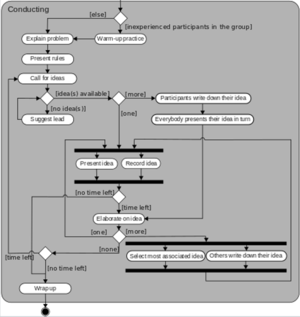
UML 1.x Activity diagram for a guided brainstorming process

source: Wikipedia
Activity Diagram: Documenting Business Use Cases[7]
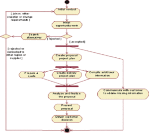
Background: A business use-case model describes the processes of a business and their interactions with external parties like customers and partners. The processes of the business are represented as business use cases, and the external parties are represented as business actors. Describing a business use case includes, among other things, giving it a name, a brief description, defining its performance goals, and its workflow. The most time-important and time-consuming aspect to describe is the workflow. Which comes first, the activity diagram or the textual description of the workflow? This is somewhat dependent on how you are used to working, and whether you "think graphically" or not. Some prefer to outline the structure visually in a diagram first, and then develop the details in the text. Others start with a bulleted list of the activity states first, and agree on those (like a step-by-step outline to the use case), then define the structure using a diagram. A valid question is also whether you really need both the textual document and the diagram. The activity diagram technique allows you to write brief descriptions of each activity state, which should make the textual specification of the workflow obsolete. Here, you need to be sensitive to your audience and the format in which they expect the specification. To understand what an activity diagram adds to the understanding of a workflow, we present a sample workflow description, and then an activity diagram for that workflow (Figure Below). This example is a proposal process, taken from an organization that sells telecom network solutions, individually configured to each customer. We have simplified the example by removing the detailed text in most of the subsections, but tried to keep enough so you can understand the structure of the workflow.
An Activity Diagram for the Business Use Case Proposal Process

source: IBM
Advantages and Disadvantages of using Activity Diagrams[8]
- Activity diagrams' advantages include that they are typically easily comprehensible for both analysts and stakeholders. According to Podeswa in UML for the IT Business Analyst, "The activity diagram is the one most useful to the IT BA for depicting workflow [because] it is simple to understand for both for BAs and end-users." Because they are among the most user-friendly diagrams available, they are generally regarded as an essential tool in an analyst's repertoire.
- Additionally, as stated above, activity diagrams allow an analyst to display multiple conditions and actors within a workflow through the use of swimlanes. Swimlanes, however, are optional as a single condition or actor is normally displayed without them.
- Their disadvantages include that they have the potential to become overly complex because their user-friendly nature may lend itself to an all-inclusive description. In other words, since it is so simple to display the information related to the project, why not include all of it? When an analyst has a large project, creating a single, overly complex diagram can be a temptation. But as one author notes, "if you are using activity diagrams to define the structure of a workflow, you should not attempt to explore several levels of activity graphs down to their most ‘atomic' level.'" Instead, an analyst should try to present a new diagram for each workflow, or if more applicable, to use swimlanes to present different actors within the same workflow.
- Another aspect of activity diagrams is that they may not be used in lieu of a state diagram or sequence diagram because "activity diagrams do not give detail about how objects behave or how objects collaborate." This is not a disadvantage per se, but it is important for an analyst to keep in mind when applying diagrams to their work.
In conclusion, activity diagrams are fairly easy to get the hang of, and will be useful for most projects because they "simply and quite plainly show how things work." Unlike many diagramming techniques, activity diagrams also enable the depiction of multiple choices and actors within a workflow, and they are easy for even non-technical users to follow.
References
- ↑ Definition - What does Activity Diagram mean? Techopedia
- ↑ Purpose of Activity Diagrams Tutorialspoint
- ↑ Relationship to Other Diagrams MSDN
- ↑ Creating Activity Diagrams Gentleware
- ↑ Basic Rules for Creating Activity Diagrams ModernAnalyst
- ↑ UML Activity Diagram: Design Elements ConceptDraw
- ↑ Activity Diagram: Documenting Business Use Cases IBM
- ↑ What are the advantages and disadvantages of using activity diagrams? modernanalyst.com
Further Reading
- Workflow Modeling With UML Activity Diagrams BA Times
- Activity Diagrams : A Formal Framework to Model Business Processes and Code Generation Journal of Object Technology
- Using Activity Diagrams to Model Systems Analysis Techniques: Teaching What We Preach Questia
- A Framework for Modeling and Analysis UML Activity Diagram using Graph Transformation ScienceDirect
- Case Report: Activity Diagrams for Integrating Electronic Prescribing Tools into Clinical Workflow NCBI
