Object Diagram
An Object Diagram can be referred to as a screenshot of the instances in a system and the relationship that exists between them. Since object diagrams depict behavior when objects have been instantiated, we are able to study the behavior of the system at a particular instant. Object diagrams are vital to portray and understand functional requirements of a system. In other words, “An object diagram in the Unified Modeling Language (UML), is a diagram that shows a complete or partial view of the structure of a modeled system at a specific time.”[1]
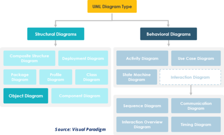
Object is an instance of a class in a particular moment in runtime that can have its own state and data values. Likewise a static UML object diagram is an instance of a class diagram; it shows a snapshot of the detailed state of a system at a point in time, thus an object diagram encompasses objects and their relationships which may be considered a special case of a class diagram or a communication diagram.<Explaining Object Diagram Visual Paradigm</ref>
Overview of Object Diagrams[2]
In the Unified Modeling Language (UML), an object diagram focuses on some particular set of objects and attributes, and the links between these instances. A correlated set of object diagrams provides insight into how an arbitrary view of a system is expected to evolve over time. In early UML specifications the object diagram is described as:
- "An object diagram is a graph of instances, including objects and data values. A static object diagram is an instance of a class diagram; it shows a snapshot of the detailed state of a system at a point in time. The use of object diagrams is fairly limited, namely to show examples of data structure."
The latest UML 2.5 specification does not explicitly define object diagrams, but provides a notation for instances of classifiers.
Object diagrams and class diagrams are closely related and use almost identical notation. Both diagrams are meant to visualize static structure of a system. While class diagrams show classes, object diagrams display instances of classes (objects). Object diagrams are more concrete than class diagrams. They are often used to provide examples or act as test cases for class diagrams. Only aspects of current interest in a model are typically shown on an object diagram.
Components of Object Diagram[3]
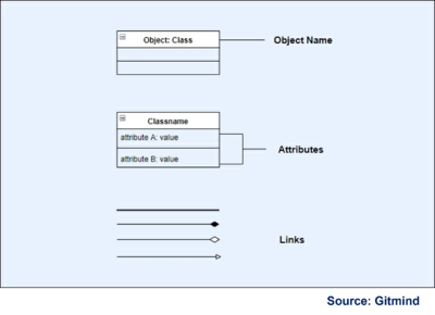
There are three major elements in the notation of an Object Diagram:
- Object Names: Like any object in a UML diagram, a rectangle usually represents objects. The rectangle comes with two rows where the object name is located at the top row of the symbol.
- Attributes: In the context of UML, attributes are the data in a class with values assigned for them. They have a separate compartment which is at the bottom row of the rectangular symbol.
- Links: The purpose of links in a UML object diagram is to show relationships of the objects with each other. Actually, there are four links used for this diagram. These include straight line, composition, generalization, and aggregation. The most utilized link, however, is the solid, straight line.
Purpose of Object Diagrams[4]
The purpose of a diagram should be understood clearly to implement it practically. The purposes of object diagrams are similar to class diagrams.
The difference is that a class diagram represents an abstract model consisting of classes and their relationships. However, an object diagram represents an instance at a particular moment, which is concrete in nature. It means the object diagram is closer to the actual system behavior. The purpose is to capture the static view of a system at a particular moment. The purpose of the object diagram can be summarized as −
- Forward and reverse engineering.
- Object relationships of a system
- Static view of an interaction.
- Understand object behavior and their relationship from practical perspective
How to Make an Object Diagram[5]
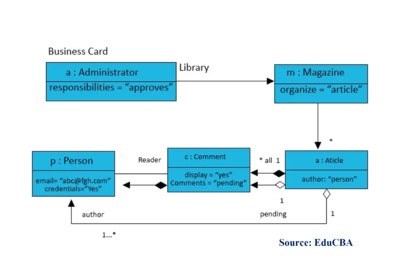
As per the above diagram:
The line between the Magazine and the Article. Messages flow from magazines to articles. That’s the arrowhead. For every one Magazine, there are many articles. The * (star) means 0 (zero) or more. The filled-in diamond represents a composition relationship, which is containment or a contains relationship. In the code, one object would actually contain another object, not a reference to an object but the object itself. In other words, the Magazine contains articles.
It contains should be destroyed as well. A Magazine has a dictionary, it contains a dictionary of articles indexed by the author, and an author is a person object. In other words, this is effectively a hash table. UML call, this is a qualified association. So in every qualified association: a key (attribute) and value. The object indexed by a key, and the object itself is the associated value.
Example:
class Magazine {
private static instance = new Library();
public static instance() { return instance;  }
private HashMap<Person, Article> articles;
public void displayPendingComments()……
public void iAmApproved (Comment pending)…..
In the object diagram, list the responsibilities, not individual methods
Examples of Object Diagrams[6]
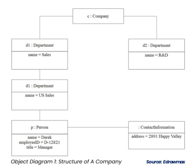
Here is an example of object diagrams illustrating a company's structure, from which there are mainly two departments - The sales department and the R&D department.
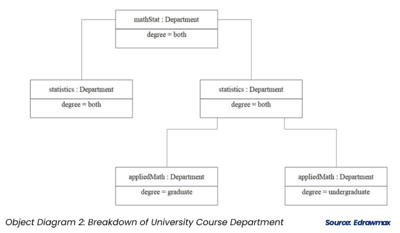
The example 2 demonstrate the university course department. For the math statics, it divided by graduate and undergraduate
Other UML Object Diagram Examples[7]
UML specifications typically don't change when you describe an object diagram in different programming languages. The whole purpose of UML is for developers to plan out software independent of specific platforms. Below are two of the most commonly used types of object diagrams in different programming languages.
- Objective C object diagram: Objective C has become very popular since Apple's release of "Objective C 2.0," and now it's the programming language of choice for Apple marketplace applications. Most people who use Objective C object diagrams are attempting to show instances for an iPhone app.
- Java object diagram: There are object diagrams that can be used in UML to describe instances that would ultimately be programmed in Java, and there are diagrams that describe Java objects that have nothing to do with UML. Whether you are looking for the former or the latter, Lucidchart can help you map the structure you need to create
Applications of Object Diagrams[8]
The following are the application areas where the object diagrams can be used.
- To build a prototype of a system.
- To model complex data structures.
- To perceive the system from a practical perspective.
- Reverse engineering.
References
- ↑ Definition - What does Object Diagram in UML Mean? Geeks for Geeks
- ↑ Overview of Object Diagrams Wikipedia
- ↑ Symbols and Notations of an Object Diagram Gitmind
- ↑ What is the Purpose of Object Diagrams? Tutorials Point
- ↑ Examples of how to make an Object Diagram EduCBA
- ↑ The Examples of Object Diagrams Edrawmax
- ↑ Other UML Object Diagram Examples Lucidchart
- ↑ What are the Applications of Object diagrams? Java T Point

