Network Topology
Network Topology refers to the physical or logical layout of a network. It defines the way different nodes are placed and interconnected with each other. Alternately, network topology may describe how the data is transferred between these nodes.[1]
A network topology diagram shows how the elements of a computer network are arranged. It allows you to visualize how different nodes are connected and how they communicate
Categories of Network Topology[2]
Two basic categories of network topologies exist, physical topologies and logical topologies.
- Physical Topology: The transmission medium layout used to link devices is the physical topology of the network. For conductive or fiber optical mediums, this refers to the layout of cabling, the locations of nodes, and the links between the nodes and the cabling. The physical topology of a network is determined by the capabilities of the network access devices and media, the level of control or fault tolerance desired, and the cost associated with cabling or telecommunication circuits.
- Logical Topology: In contrast, logical topology is the way that the signals act on the network media, or the way that the data passes through the network from one device to the next without regard to the physical interconnection of the devices. A network's logical topology is not necessarily the same as its physical topology. For example, the original twisted pair Ethernet using repeater hubs was a logical bus topology carried on a physical star topology. Token ring is a logical ring topology, but is wired as a physical star from the media access unit. Physically, AFDX can be a cascaded star topology of multiple dual redundant Ethernet switches; however, the AFDX Virtual links are modeled as time-switched single-transmitter bus connections, thus following the safety model of a single-transmitter bus topology previously used in aircraft. Logical topologies are often closely associated with media access control methods and protocols. Some networks are able to dynamically change their logical topology through configuration changes to their routers and switches.
Models of Physical and Logical Network Topology[3]
The physical and logical network topologies of a network do not necessarily have to be identical. However, both physical and network topologies can be categorized into the following models:
- Point-to-Point
Point-to-point networks contains exactly two hosts such as computer, switches or routers, servers connected back to back using a single piece of cable. Often, the receiving end of one host is connected to sending end of the other and vice-versa.
If the hosts are connected point-to-point logically, then may have multiple intermediate devices. But the end hosts are unaware of underlying network and see each other as if they are connected directly.
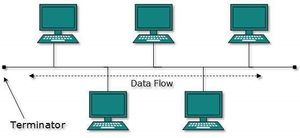
- Bus Topology
In case of Bus topology, all devices share single communication line or cable.Bus topology may have problem while multiple hosts sending data at the same time. Therefore, Bus topology either uses CSMA/CD technology or recognizes one host as Bus Master to solve the issue. It is one of the simple forms of networking where a failure of a device does not affect the other devices. But failure of the shared communication line can make all other devices stop functioning.
Both ends of the shared channel have line terminator. The data is sent in only one direction and as soon as it reaches the extreme end, the terminator removes the data from the line.
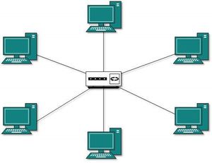
- Star Topology
All hosts in Star topology are connected to a central device, known as hub device, using a point-to-point connection. That is, there exists a point to point connection between hosts and hub. The hub device can be any of the following: Layer-1 device such as hub or repeater Layer-2 device such as switch or bridge Layer-3 device such as router or gateway
As in Bus topology, hub acts as single point of failure. If hub fails, connectivity of all hosts to all other hosts fails. Every communication between hosts, takes place through only the hub.Star topology is not expensive as to connect one more host, only one cable is required and configuration is simple.
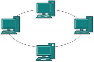
- Ring Topology
In ring topology, each host machine connects to exactly two other machines, creating a circular network structure. When one host tries to communicate or send message to a host which is not adjacent to it, the data travels through all intermediate hosts. To connect one more host in the existing structure, the administrator may need only one more extra cable.
Failure of any host results in failure of the whole ring.Thus, every connection in the ring is a point of failure. There are methods which employ one more backup ring.
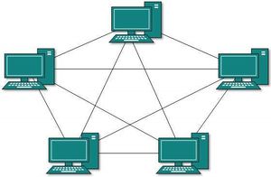
- Mesh Topology
In this type of topology, a host is connected to one or multiple hosts.This topology has hosts in point-to-point connection with every other host or may also have hosts which are in point-to-point connection to few hosts only. Hosts in Mesh topology also work as relay for other hosts which do not have direct point-to-point links.
Mesh technology comes into two types:
- Full Mesh: All hosts have a point-to-point connection to every other host in the network. Thus for every new host n(n-1)/2 connections are required. It provides the most reliable network structure among all network topologies.
- Partially Mesh: Not all hosts have point-to-point connection to every other host. Hosts connect to each other in some arbitrarily fashion. This topology exists where we need to provide reliability to some hosts out of all.
- Tree Topology
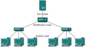
Also known as Hierarchical Topology, this is the most common form of network topology in use presently.This topology imitates as extended Star topology and inherits properties of bus topology.
This topology divides the network in to multiple levels/layers of network. Mainly in LANs, a network is bifurcated into three types of network devices. The lowermost is access-layer where computers are attached. The middle layer is known as distribution layer, which works as mediator between upper layer and lower layer. The highest layer is known as core layer, and is central point of the network, i.e. root of the tree from which all nodes fork.
All neighboring hosts have point-to-point connection between them.Similar to the Bus topology, if the root goes down, then the entire network suffers even.though it is not the single point of failure. Every connection serves as point of failure, failing of which divides the network into unreachable segment.
- Daisy Chain
This topology connects all the hosts in a linear fashion. Similar to Ring topology, all hosts are connected to two hosts only, except the end hosts.Means, if the end hosts in daisy chain are connected then it represents Ring topology.
Each link in daisy chain topology represents single point of failure. Every link failure splits the network into two segments.Every intermediate host works as relay for its immediate hosts.
- Hybrid Topology
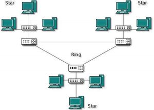
A network structure whose design contains more than one topology is said to be hybrid topology. Hybrid topology inherits merits and demerits of all the incorporating topologies.
The above picture represents an arbitrarily hybrid topology. The combining topologies may contain attributes of Star, Ring, Bus, and Daisy-chain topologies. Most WANs are connected by means of Dual-Ring topology and networks connected to them are mostly Star topology networks. Internet is the best example of largest Hybrid topology
Note: All Diagrams above are sourced from Tutorials Point
Advantages and Problems with Network Topology Modules[4]
Mesh Topology
- Advantages of this topology :
- It is robust.
- Fault is diagnosed easily. Data is reliable because data is transferred among the devices through dedicated channels or links.
- Provides security and privacy.
- Problems with this topology :
- Installation and configuration is difficult.
- Cost of cables are high as bulk wiring is required, hence suitable for less number of devices.
- Cost of maintenance is high.
Star Topology
- Advantages of this topology :
- If N devices are connected to each other in star topology, then the number of cables required to connect them is N. So, it is easy to set up.
- Each device require only 1 port i.e. to connect to the hub.
- Problems with this topology :
- If the concentrator (hub) on which the whole topology relies fails, the whole system will crash down.
- Cost of installation is high.
- Performance is based on the single concentrator i.e. hub.
Bus Topology
- Advantages of this topology :
- If N devices are connected to each other in bus topology, then the number of cables required to connect them is 1 which is known as backbone cable and N drop lines are required.
- Cost of the cable is less as compared to other topology, but it is used to built small networks.
- Problems with this topology :
- If the common cable fails, then the whole system will crash down.
- If the network traffic is heavy, it increases collisions in the network. To avoid this, various protocols are used in MAC layer known as Pure Aloha, Slotted Aloha, CSMA/CD etc.
Ring Topology
- Advantages of this topology :
- The possibility of collision is minimum in this type of topology.
- Cheap to install and expand.
- Problems with this topology :
- Troubleshooting is difficult in this topology.
- Addition of stations in between or removal of stations can disturb the whole topology.
Tree Topology[5]
- Advantages of this topology :
- Extension of bus and star topologies.
- Expansion of nodes is possible and easy.
- Easily managed and maintained.
- Error detection is easily done.
- Problems with this topology :
- Heavily cabled.
- Costly.
- If more nodes are added maintenance is difficult.
- Central hub fails, network fails.
Hybrid Topology
- Advantages of this topology :
- Reliable as Error detecting and trouble shooting is easy.
- Effective.
- Scalable as size can be increased easily.
- Flexible.
- Problems with this topology :
- Complex in design.
- Costly.
See Also
Network
Network Architecture
Computer Networking
Local Area Network (LAN)
Wide Area Network (WAN)
Broad Network Access
Integrated Services Digital Network (ISDN)
Simple Network Management Protocol (SNMP)
References
- ↑ Defining Network Topology Techopedia
- ↑ What are the two basic categories of network topologies? Wikipedia
- ↑ Models of Physical and Logical Network Topology Tutorials Point
- ↑ Advantages and Problems with Network Topology Modules Geeks for Geeks
- ↑ Advantages and Disadvantages of Network Topologies Study Tonight


